F5 Distributed Cloud Network Connect and NetApp BlueXP
Storage is a critical piece of the puzzle in every network infrastructure. At the same time, it is very sensitive, and data stored on every storage can be affected by multiple factors, including security breaches, hardware issues and many more.
So, it is very important to recover the data if it’s altered, and the best way to do this is to replicate the data on different volumes.
Another purpose for replicating the volumes is being able to perform analytics on enterprise data, making research into data trends and reduce downtime from recovery events.
With the major advances in technology from the last years, applications have extended beyond the traditional datacenter, and moved partially or totally into different environments like public or private clouds, closer to the edge, taking the data along with them.
Storage replication has followed the same path, and many companies find it best suitable to use a hybrid cloud environment for this purpose.
This article explains how to use hybrid cloud storage replication using Netapp BlueXP connector over F5 Distributed Cloud. Netapp BlueXP connector is a cloud-based control plane that allows the management of volumes both on-prem and in public cloud providers, the major benefit being data replication.
F5 Distributed Cloud Networking is an innovative multi-cloud SaaS-based networking, traffic optimization, and security service for public and private clouds through a single console, relieving operational teams from the struggle of managing cloud-dependent services and multiple third-party vendors.
The advantage of using F5 Distributed Cloud Networking is the simplification of network and application connectivity across distributed environments, like private data centers, private or public cloud, gaining insight into network, security, and app performance issues across all sites.
In this article we will explain step by step how to configure the elements needed in order for Netapp BlueXP connector to replicate the data from a Netapp device stored in our private datacenter to a Netapp device from Azure cloud.
The simplified network diagram is the following:
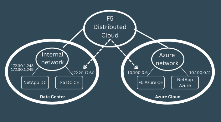
As we can see, in order for the Netapp cluster to form, there needs to be layer 3 connectivity between the local Netapp IPs and Azure Netapp IP and we will achieve this using F5 Distributed Cloud (F5 XC).
The first step is to create the connectivity between local DC and Azure environment over F5 Distributed cloud (F5 XC) and we will achieve this by creating a security demarcation point in each environment, called CE, which can be a virtualized or dedicated server appliance.
Once the layer 3 connectivity is done between the CEs, we will need to take care of routing configuration in both local, Azure, and F5 environments.
Installing the F5 DC CE
First, we will install the local CE in our data center.
For this we will need a site token which will be used by the VM after its installation to “call home”, or better said to be able to ask for registration into F5 XC, and for the F5 XC to recognize it and approve it.
A token object is used to manage site admission. User must generate token before provisioning and pass this token to site during its registration.
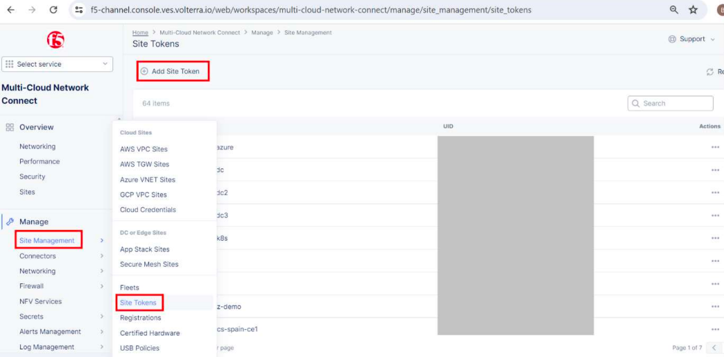
We will need to login into the F5 XC console and create a site token.
After logging in to F5 XC console, go to Multi-Cloud Network Connect
Manage -> Site management -> Site tokens and then click Add Site Token
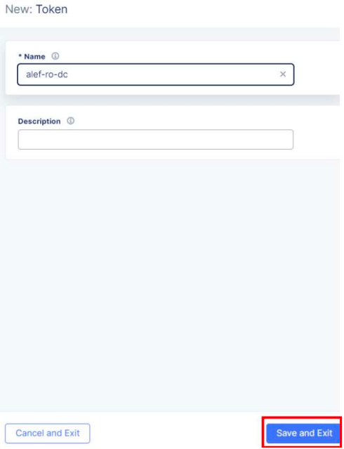

Make a note of the UID which we’ll use when installing the local CE.
This is a unique string, so it’s obvious why is hidden in the picture.
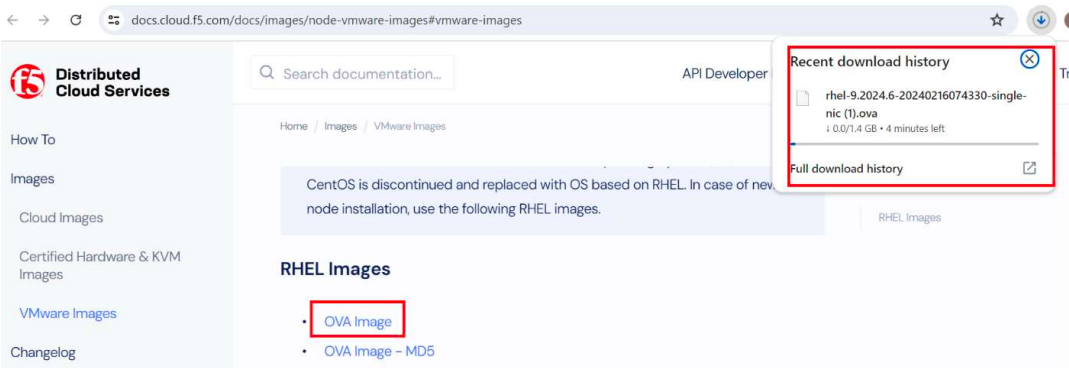
Now that we have the token we’ll proceed with installing the local VM, using a template provided by F5, which can be downloaded from here:
https://docs.cloud.f5.com/docs/images
The VM can be installed in VMware environment, as well as KVM or certified hardware.
In our environment we’re using VMware.
We’ll download the OVA image.
We need to keep in mind the requirements:
- Resources required per VM: Minimum 4 vCPUs and 16 GB RAM.
- 45 GB is the minimum amount required for storage. However, to deploy an F5® Distributed Cloud App Stack Site, 100 GB is the recommended minimum amount of storage.
We’re using VMWare vSphere and the client version is 7.0.3.x
F5 documentation is based on VMware vSphere Hypervisor (ESXi) 7.0 or later. Earlier versions might not be supported, so keep an eye on that.
The OVA file can be used to create an OVF template that can be used multiple times after that if multiple sites need to be deployed.
We will create the VM directly from the OVA file.
I will not detail the steps needed to install the VM in VMware, as the process might be different depending on everyone’s environment.
Just keep in mind that the VM needs to have Internet access and use the site token (UID) during the installation process, in order for the VM to be able to register into F5 XC.
After the VM is created, we need to power it on.

After the VM initializes, it will “call home” using the outside interface and the provided token, and we can see it in F5 XC console in Pending Registrations
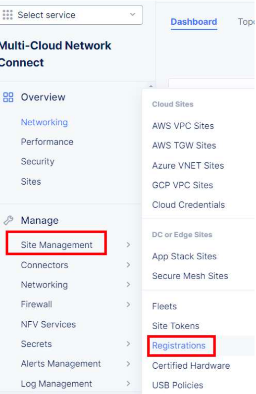
Go to Multi-Cloud Network Connect -> Manage -> Site Management -> Registrations
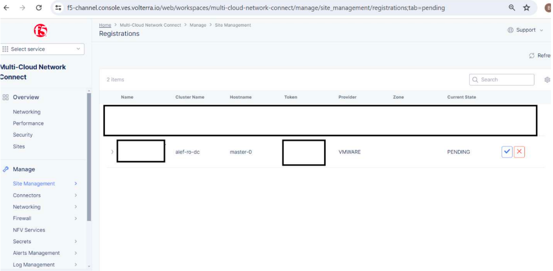
And we can see the Pending registration of our local CE site with the state of PENDING
We’ll click on the blue button and we’re presented with an overview of the settings for our local CE
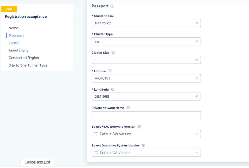
We’ll review the settings, and if all is good, we’ll click on the Save and Exit button.
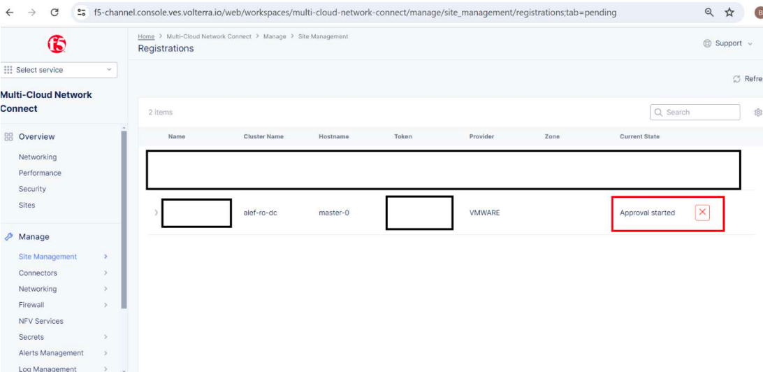
The status of our site will change to Approval started.
If we go to Overview -> Sites we can see our site being provisioned.
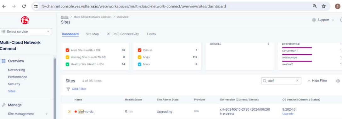
The provisioning process will take few minutes, so be patient.
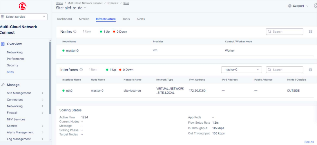
After the provisioning is done, we can see our local CE registered into F5 XC console with a score of 100.

We can check the status of the CE and see the interface name, node name, interface IP and other parameters.
When it comes to the communication between local CE and F5 XC, this is done through IPSec or SSL tunnels established after the provisioning process between the local CE and 2 REs (2 Regional Edges) that are selected based on CE’s public IP (the closest ones).
Once these REs are selected, the list of the two selected regional edges is sent to the local CE as part of the registration approval. Also, the following additional information is sent as part of this approval:
- Site identity and PKI certificates - these certificates are regularly rotated by the system
- Initial configuration to create and negotiate secure tunnels for the F5 Distributed Cloud fabric.
The local CE will try both IPSec and SSL tunnels to the selected REs. If IPSec is able to establish the connectivity, it will be preferred over SSL.
For the IPsec connection between local CE and REs, both Public Key Infrastructure (PKI) and Pre-Shared-Key (PSK) mode are supported. When using PKI, system supports RSA 2048 certificates to authenticate remote peers. The following ciphers are used:
Key Exchange: aes256-aes192-aes128, aes256gcm16
Authentication: sha256-sha384
DH groups: ecp256-ecp384-ecp521-modp3072-modp4096-modp6144-modp8192
ESP: aes256gcm16-aes256/sha256-sha384
After the tunnels are established, the Fabric will come up and distributed control plane in the RE will take over the control of the local CE. These tunnels are used for both management, control, and data traffic.
Installing the F5 AZURE CE
For deploying the Azure F5 CE site, we need to take into consideration the needed resources:
- Resources required per node:
-vCPUs: Minimum 4 vCPUs
-Memory: 14 GB RAM
-Disk storage:
~Minimum 45 GB for Mesh site.
~Minimum 100 GB for App Stack site. - UDP port 6080 needs to be opened between all the nodes of the site.
- Internet Control Message Protocol (ICMP) needs to be opened between the CE nodes on the Site Local Outside (SLO) interfaces. This is needed to ensure intra-cluster communication checks.
The first thing is to create a token in the F5 XC console which will be used when deploying the image in Azure, similar to the process we followed for the local CE site token.
So we’ll repeat the steps followed when we created the token for the local CE.
Log into the XC console, go to MulƟ Cloud Network Connect, Manage -> Site Management -> Site Tokens -> Add Site Token.
We’ll make a note on the UID for the new Azure site.
Now we need to create the resources in Azure needed for the VM deployment so we’ll log into our Azure account.
Again, I will not detail the process for creating the VM in Azure, as this might differ from environment to environment, but basically, we’ll need to create the needed resources.
These are the service principal, and a new custom role, which we’ll associate with the Service principal, we’ll need to assign the role to the Service principal and make sure that the F5 machine will have access to our Azure subscription through the custom role and service principal.
For the custom role, we’ll use the JSON template provided by F5:
{
"properties": {
"roleName": "F5-To-Azure-CustomRole",
"description": "F5 XC Custom Role to create Azure VNET site",
"assignableScopes": [
"/subscriptions/YourSubscriptionId"
],
"permissions": [
{
"actions": [
"*/read",
"*/register/action",
"Microsoft.Compute/disks/delete",
"Microsoft.Compute/skus/read",
"Microsoft.Compute/virtualMachineScaleSets/delete",
"Microsoft.Compute/virtualMachineScaleSets/write",
"Microsoft.Compute/virtualMachines/delete",
"Microsoft.Compute/virtualMachines/write",
"Microsoft.MarketplaceOrdering/agreements/offers/plans/cancel/action",
"Microsoft.MarketplaceOrdering/offerTypes/publishers/offers/plans/agreements/write",
"Microsoft.Network/loadBalancers/backendAddressPools/delete",
"Microsoft.Network/loadBalancers/backendAddressPools/join/action",
"Microsoft.Network/loadBalancers/backendAddressPools/write",
"Microsoft.Network/loadBalancers/delete",
"Microsoft.Network/loadBalancers/write",
"Microsoft.Network/locations/setLoadBalancerFrontendPublicIpAddresses/action",
"Microsoft.Network/networkInterfaces/delete",
"Microsoft.Network/networkInterfaces/join/action",
"Microsoft.Network/networkInterfaces/write",
"Microsoft.Network/networkSecurityGroups/delete",
"Microsoft.Network/networkSecurityGroups/join/action",
"Microsoft.Network/networkSecurityGroups/securityRules/delete",
"Microsoft.Network/networkSecurityGroups/securityRules/write",
"Microsoft.Network/networkSecurityGroups/write",
"Microsoft.Network/publicIPAddresses/delete",
"Microsoft.Network/publicIPAddresses/join/action",
"Microsoft.Network/publicIPAddresses/write",
"Microsoft.Network/routeTables/delete",
"Microsoft.Network/routeTables/join/action",
"Microsoft.Network/routeTables/write",
"Microsoft.Network/virtualHubs/delete",
"Microsoft.Network/virtualHubs/bgpConnections/delete",
"Microsoft.Network/virtualHubs/bgpConnections/read",
"Microsoft.Network/virtualHubs/bgpConnections/write",
"Microsoft.Network/virtualHubs/ipConfigurations/delete",
"Microsoft.Network/virtualHubs/ipConfigurations/read",
"Microsoft.Network/virtualHubs/ipConfigurations/write",
"Microsoft.Network/virtualHubs/read",
"Microsoft.Network/virtualHubs/write",
"Microsoft.Network/virtualNetworks/delete",
"Microsoft.Network/virtualNetworks/peer/action",
"Microsoft.Network/virtualNetworks/subnets/delete",
"Microsoft.Network/virtualNetworks/subnets/join/action",
"Microsoft.Network/virtualNetworks/subnets/read",
"Microsoft.Network/virtualNetworks/subnets/write",
"Microsoft.Network/virtualNetworks/virtualNetworkPeerings/write",
"Microsoft.Network/virtualNetworks/virtualNetworkPeerings/delete",
"Microsoft.Network/virtualNetworks/write",
"Microsoft.Network/virtualNetworkGateways/delete",
"Microsoft.Network/virtualNetworkGateways/read",
"Microsoft.Network/virtualNetworkGateways/write",
"Microsoft.Resources/subscriptions/locations/read"
"Microsoft.Resources/subscriptions/resourcegroups/delete",
"Microsoft.Resources/subscriptions/resourcegroups/read",
"Microsoft.Resources/subscriptions/resourcegroups/write"
],
"notActions": [],
"dataActions": [],
"notDataActions": []
}
]
}
}
When creating the Service Principal, take a note on the Application ID which is the Client ID we’ll need later when creating the Azure site in the F5 XC console.
We’ll also need the Subscription ID which can be found in the portal.
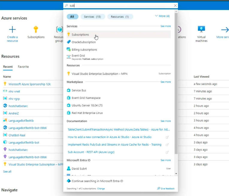
We’ll also need the Tenant ID which we can find in Entra ID
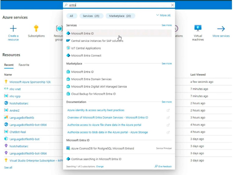
After all the resources are created, we’ll need to deploy the VM into Azure.
For this We need to create a Resource group, with a name and region and for the image, we’ll use the one provided by F5.
The next step is to create the VNET where we’ll create the frontend and backend which will be related to the interfaces we’ll see in the F5 XC console. Notice that the back-end is in the same subnet as the Netapp Azure subnet.

For Custom Data we’ll add the script provided by F5:
#cloud-config
write_files:
# /etc/hosts
- path: /etc/hosts
content: |
# IPv4 and IPv6 localhost aliases
127.0.0.1 localhost
::1 localhost
127.0.0.1 vip
permissions: '0644'
owner: root
# /etc/vpm/config.yaml
- path: /etc/vpm/config.yaml
permissions: '0644'
owner: root
content: |
Vpm:
ClusterType: ce
Token: 222222v2-333e-44n4-55j5-k6kkkk7777k7
MauricePrivateEndpoint: https://register-tls.ves.volterra.io
MauriceEndpoint: https://register.ves.volterra.io
CertifiedHardwareEndpoint: https://vesio.blob.core.windows.net/releases/certified-hardware/azure.yml
Kubernetes:
EtcdUseTLS: True
Server: vip
For the token, we’ll add the UID created earlier.
The VM will look similar to this.
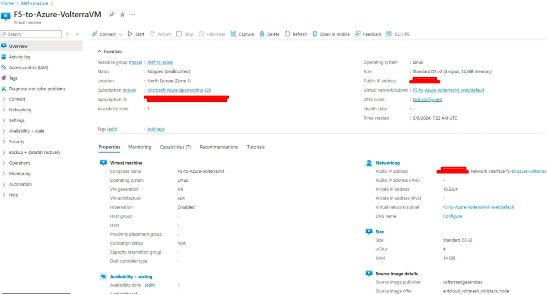
Now we need to create the Azure F5 CE site in F5 XC
For this we’ll log into our F5 XC account, go to Multi-Cloud Network Connect, go to Manage - > Site Management -> Azure VNET Sites, and Add Azure VNET Site
We’ll need to give a site name.
For Site Type Selection, under Cloud Credentials we need to create new credentials. So click on New item, and we’ll give a name, for Credential Type we’ll use Azure Client Secret for Service Principal and we’ll use the Client ID, Subscription ID, and Tenant ID we’ve seen earlier.
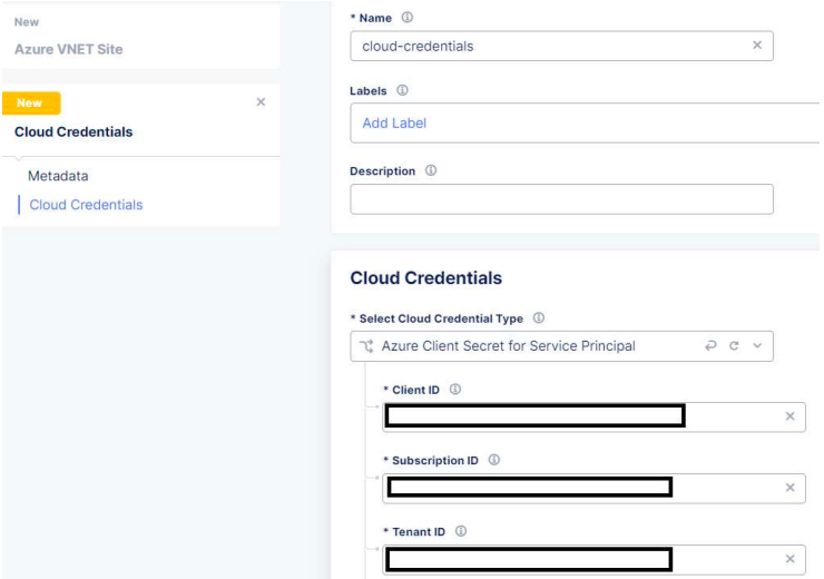
We also need to configure the Azure Client Secret
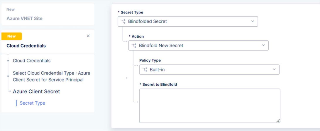
For Secret to Blindfold we’ll use the Secret ID from the Service Principal.
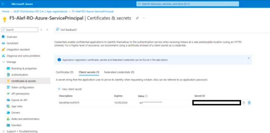
Next, we’ll select the resource group from Azure, the region type and name, and for VNET select Existing Vnet , the vnet Resource Group, and Vnet name – all these are the ones from Azure, that we’ve created earlier.
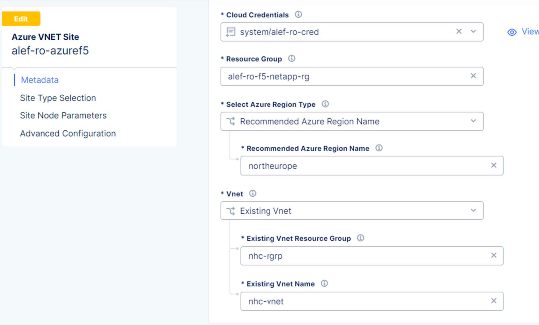
Under Select Ingress Gateway or Ingress/Egress Gateway we’ll select Ingress/Egress Gateway (Two interface) and click on Configure

We’ll use the default Azure Certified Hardware and click on Add Item
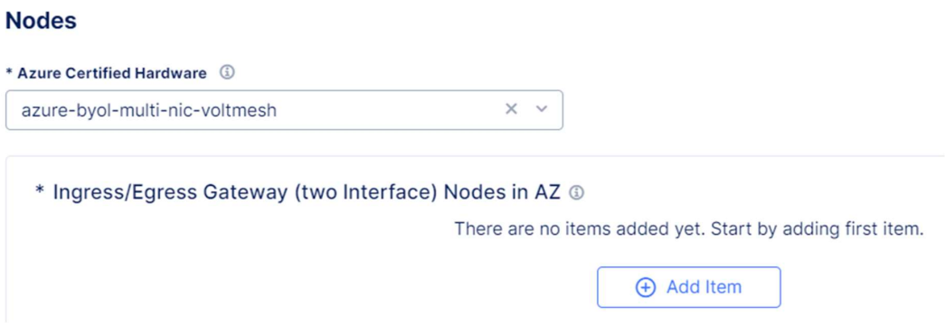
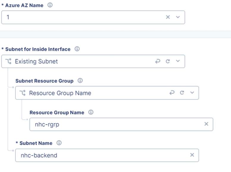
Select the Azure AZ Name like we have it in Azure, choose Existing Subnet for Inside interface, select the resource group name and for subnet name enter the name of the back-end interface – this will be in the same subnet as the Azure Netapp.
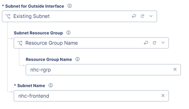
For the outside interface repeat the steps and for the name enter the frontend interface.
We now need to enter the Site Node Parameters, where for the public ssh key we’ll use the public key from Azure.
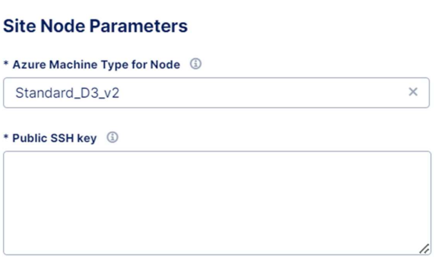
Save & Exit and the Azure site is created and provisioned.

Routing configuration
Now that we have both CEs installed, we need to configure routing in order for the local NetApp to be able to “see” the Azure NetApp.
At this moment none of the CEs is aware of the local subnet of the other CE, and in order to achieve this, each CE must “publish” their subnets into a global network.
Think, for example, of a company with multiple branches, where each branch must “tell” the HQ the subnets it has.
The F5 XC console offers some very useful tools to troubleshoot and diagnose the site’s connectivity like Show Routes, Flow table, Ping, Tcpdump, and Traceroute and also offers the possibility to reboot the device or just a soft restart.
One of these tools is Show Routes and is available if we click on our site and check the Tools tab.
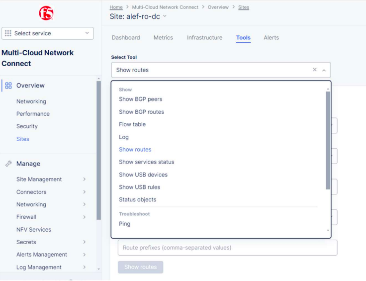
If we check the routes for the local CE, we can see only the default and directly connected routes.
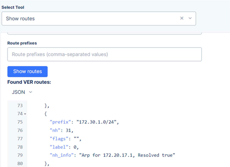
We can’t see the route to 172.30.1.0/24 yet.
If we check the Azure F5 CE routing table, we’ll also only see the connected routes, 10.100.0.0/24.
To create the proper routing, what we need to do on the local CE is to publish the outside interface to our global network, and for the Azure CE to publish the inside interface to our global network.
This is because the local F5 CE is created with a single interface (outside), and the Azure F5 CE is created with 2 interfaces (outside and inside), with the inside interface connected to the same VNET as the Azure Netapp.
In order to achieve this, we first need to create our global network. This is a Virtual Network that we’ll use to publish our subnets.
We need to go to Manage -> Networking -> Virtual Networks and click on Add Virtual Network.
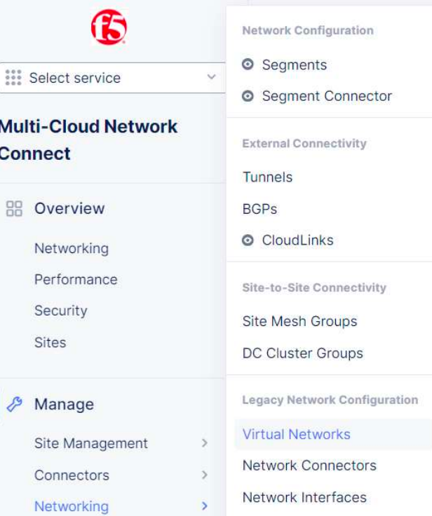
We need to give a name and select type Global Network.
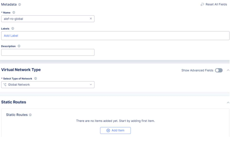
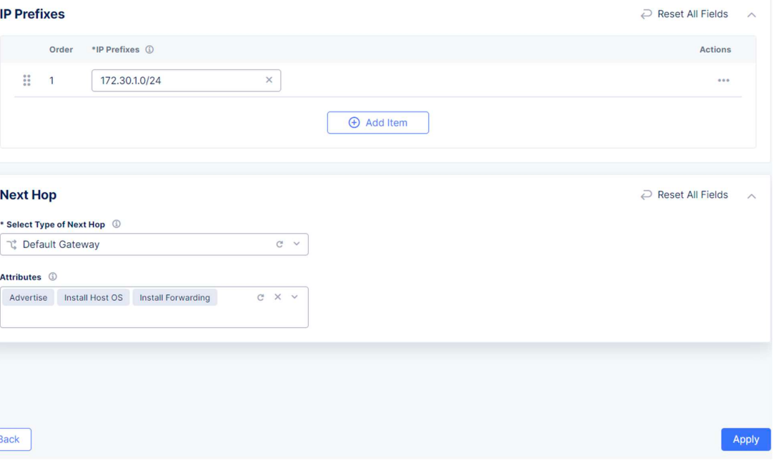
Also, as the 172.30.1.0/24 subnet is not directly connected to the local CE, we will publish this subnet to the Global Network as well, using a static route.
We’ll click on Add item under Static Routes and set the prefix and the Default Gateway as Next Hop. Also, we can set up Attributes.
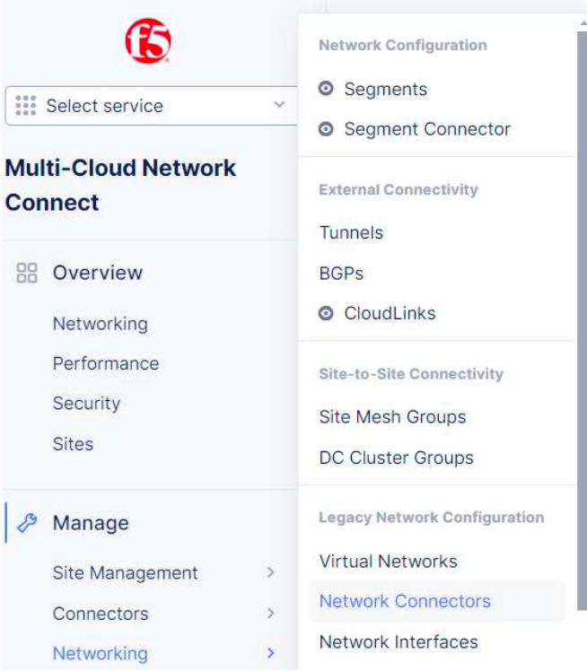
The next step is to create a network connector which will connect our local site to the global network.
We need to go to Manage -> Networking -> Network Connectors and click on Add Network Connector.
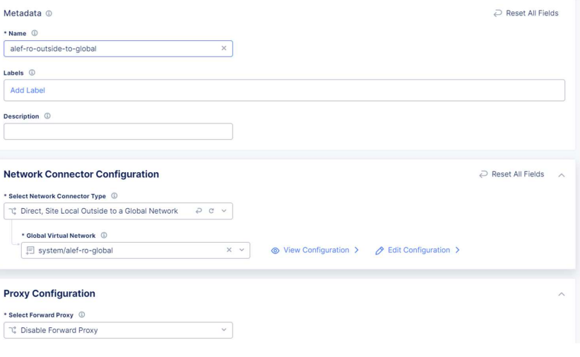
We need to give a name and for the connector type we’ll choose Direct, Site Local Outside to Global Network (remember, the local CE has only one outside interface) and select the global network we’ve created earlier.
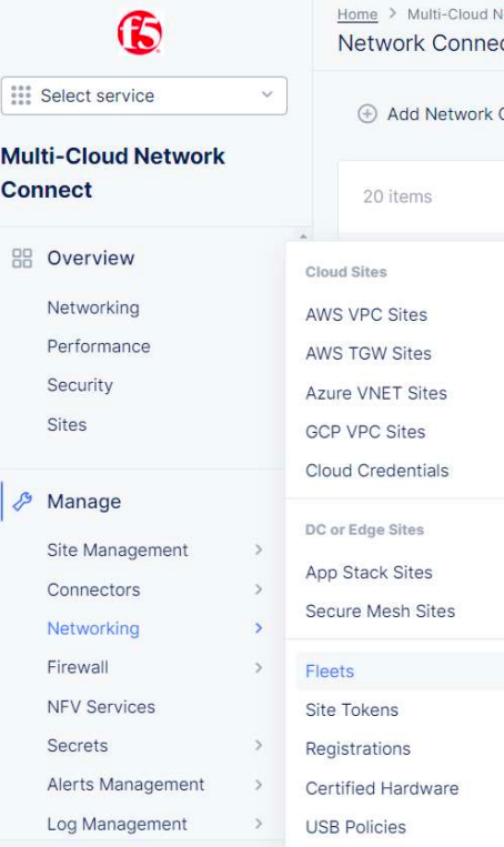
Next we need to create our fleet, where we’ll add all the objects we’ve created so far.
We need to go to Manage -> Site Management -> Fleets and click on Add Fleet
We need to give a fleet name, fleet label value which can be the same as the name. For Outside Virtual Network select the global network we’ve created earlier and for Network Connectors select the connector we’ve created at the previous step.
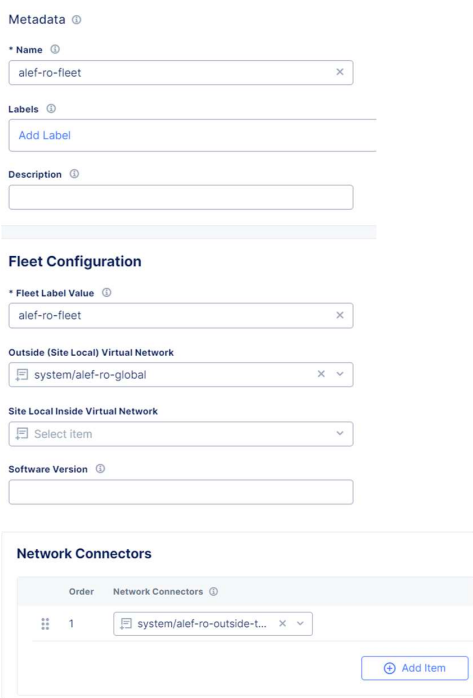
Here we can enable a Network Firewall, or block services that are not allowed into our Global Network. We’ll leave the default values for now.
We now need to add the fleet to our local CE as a label.
So we’ll edit our site.

And under Labels we’ll add the ves.io/fleet label with the value of the fleet we created earlier.

We can now check the routing table for the local CE and see that we can see the route to 172.30.1.0/24.
Ping from local CE to NetApp DC now works:
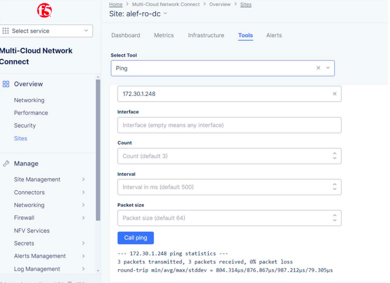
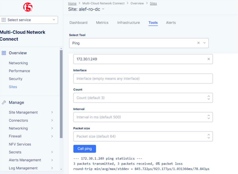
Still, we don’t have the route to Azure NetApp yet.
Now we need to take care of routing for the Azure F5 CE – as we’ve seen before, we only have the direct connected routes in the routing table, and what we want to see in the routing table as well are the routes to 172.20.17.0/24 and 172.30.1.0/24.
We’ll achieve this by “connecting” the Azure F5 CE to our global network and publish the inside interface to the global network.
We need to edit the Azure CE’s configuration.
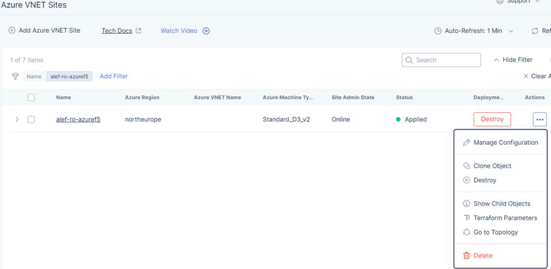
For the Ingress/Egress Gateway select Edit Configuration

Under Advanced Options choose Connect Global Networks for the Select Global Networks to Connect option and add the global network we’ve created earlier (make sure you enable the Show Advanced Fields option)

We also need to take care of routing configuration in Azure.
For this we’ll login into our Azure account and create a route table.
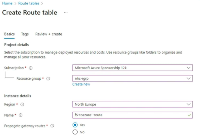
Then we’ll add the routes to the local CE subnet and local Netapp subnet.
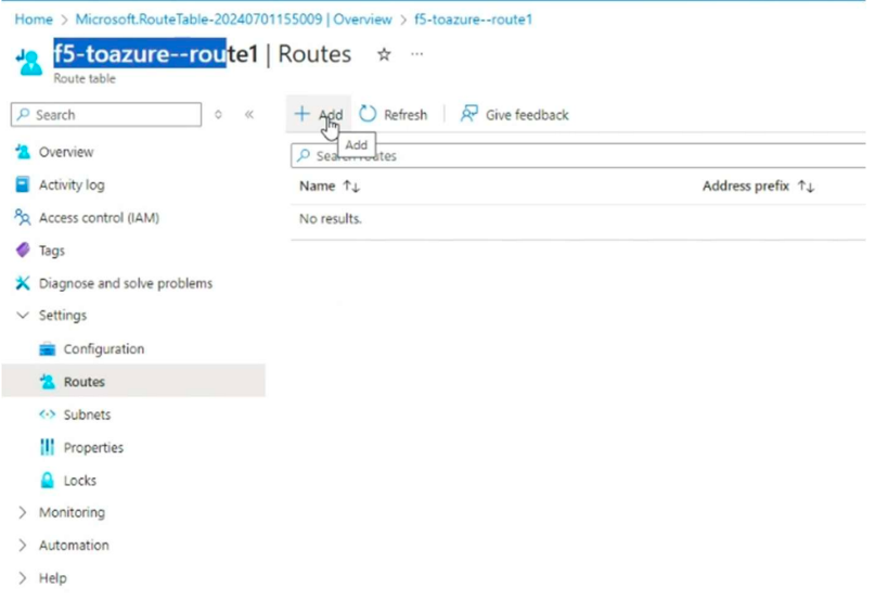
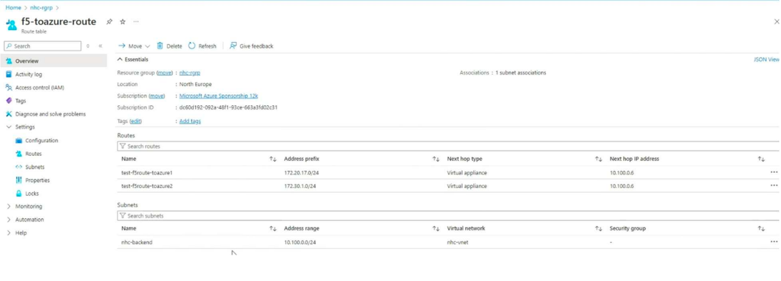
Aaaaaand that’s it!
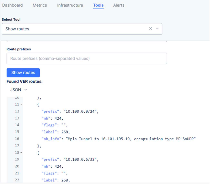
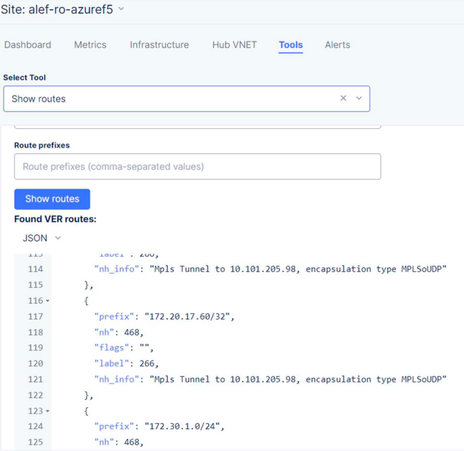
We can now check the routing table for both CEs and see that we have set up the proper routing.
Local CE:
Azure CE:
So, with the proper routing in place, let’s check if the Netapp devices can “see” each other.
Ping from Netapp DC to Azure NetApp:

Ping from Azure NetApp to NetApp DC:

Now let’s check the NetApp environment.
We’ll log in to our Azure NetApp environment.
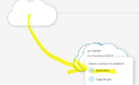
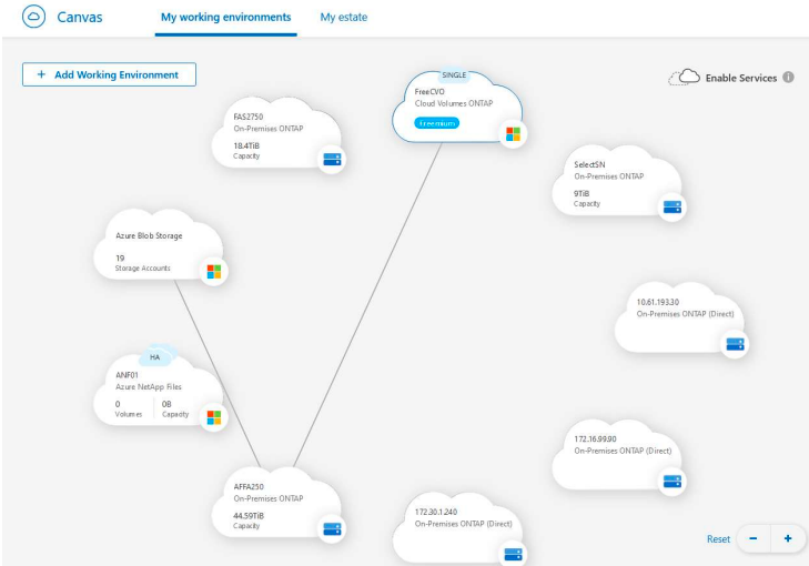
Drag the Onprem Storage over CVO pictogram .
A small popup showing actions will appear > select Replication
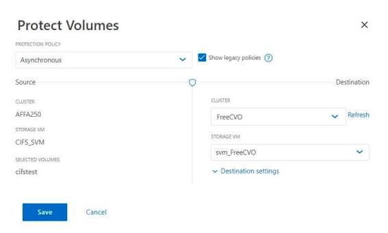
We can see the cluster:
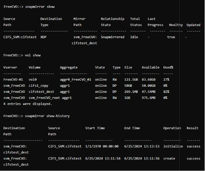
We’ll login on CLI and check the status.

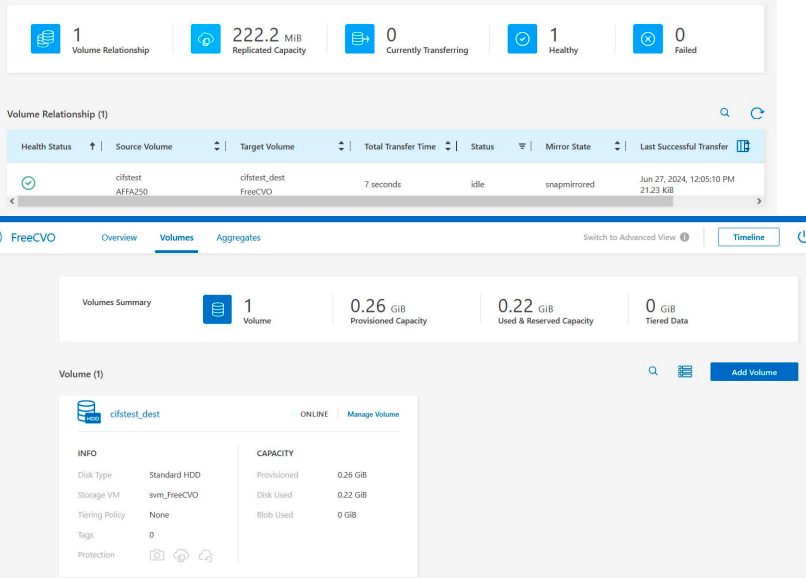
Now we’ll transfer a small amount of data between Netapps and we can see that the transfer is successful.
So this document explains how we can use the F5 XC Multi-Cloud Network Connect to connect two different environments, one on-premises and one in Azure public cloud.
